
What? Why?
Before going into the details about wiring a relay, what is it? And why do you need one?
There are two advantages of using a relay.
The first advantage is in reducing the thickness of wire required.
Let's say you're going to be adding auxiliary driving lights. The simplest way of doing this would be to take a fairly thick wire from the positive terminal of the battery to the lights, and another fairly thick wire from the lights to the negative battery terminal. However, that means the lights are on all the time, so obviously an on/off switch is needed. So now your wiring would be positive terminal → switch → lights → negative terminal.
So far so good. But what happens if there's a short circuit somewhere accidentally? This would cause your new (probably expensive) lights to fry. So you need a fuse as well.
Now we get into the mathematics of electricity. For argument's sake let's say each of the two auxiliary lights is 120W. So what size fuse is needed? Well, Power = Volts x Amps. So the Amperage or current strength in this particular application is 240W (there are two lights) divided by 12 (the battery voltage). This gives us 20A.
Now the idea is to make the fuse the "weak point" in the circuit, so that the fuse is the first thing to melt if there is a problem. However, we can't just use a 20A fuse. When switching on a circuit, a cold light bulb will use more current than a hot one (and similarly it takes more current to start a motor than to keep it turning). A good rule of thumb is to add 30%. So 20 x 1.3 gives us 26A. Automotive fuses aren't available at this rating; but the closest is 25A.
The next consideration is the size and length of wire. The longer the wire, the more the voltage drop. And the thinner the wire, the less current it can carry. There are various online calculators which will enable you to determine the wire thickness required. In this case, if we assume that the length is 1.8m (6 feet), the thinnest wire size we could use would be 14 gauge (1.6mm diameter, 2.1mm2 in cross sectional area).
That's actually fairly thick. But by using a relay, much thinner wire can be used. All a relay does is act as a separate "switch".
The second advantage of using a relay is that it can be wired so that the circuit only goes "live" when the ignition is switched on. This means if your ST1100 is left unattended, you won't return to your bike to find that your battery is flat because some sticky-fingered schoolboy has switched on all your auxiliary lights and other farkles.
Each relay has two circuits; a light-duty switching circuit which controls a different heavy-duty circuit. In our auxiliary lighting example above, the light-duty switching circuit is controlled by the on/off switch. This in turn controls the heavy-duty circuit which feeds the lights. So the thick wire which is needed for the lights go directly from the battery positive to the relay, and from the relay to the lights. A much thinner wire can then be used from the relay to the on/off switch.
Wiring
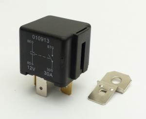
There are different sorts of relays - but the most commonly used in automotive applications has 4 connectors, usually labelled 30, 85, 86, and 87 (a 5-connector relay also has a terminal labelled 87a - this terminal can be ignored for our situation).
Now in our simplified example for auxiliary lights, you'll need a length of 14 gauge red wire, a length of 14 gauge black wire, a length of thinner red wire (perhaps 22 gauge), and a length of black wire of the same gauge.
- Run a length of 14 gauge red wire from the battery positive terminal to the fuse.
- From the fuse run a length of 14 gauge red wire to the relay terminal labelled "30".
- Run a length of 14 gauge red wire from relay terminal "87" to one connector on each of the auxiliary lights.
- Now run a length of 14 gauge black wire from each of the remaining auxiliary light terminals to a suitable earth point.
- Run a length of 22 gauge red wire from the relay terminal labelled "86" to one side of your on/off switch.
- From the other side of the on/off switch run a length of 22 gauge red wire to a connection which becomes "live" when the ignition is switched on (the relay is only going to be drawing around 100 milliamps, so it won't affect the circuit you tap into). This way your on/off switch will only be operational when the ignition is on.
- Finally, using a length of 14 gauge black wire, connect the relay terminal labelled "85" to a suitable earth point.
(Yes, two earthing points are required; these can be attached at the same place, or at different points, it doesn't matter).
Obviously before carrying out this procedure, the ignition should be switched off. It is also safest to disconnect the battery before doing any additional wiring. Decide upon the location of the relay - it's usually placed near the battery, but can also be put under the seat, or even closer to the auxiliary lights. It should be secure though; you don't want it rattling about.
Once everything is in place, disconnect the wire from relay terminal "87" before reconnecting the battery. Switch the ignition on, and operate the on/off switch. You may hear a "click" from the relay. Using a multimeter (or even a 12V bulb) test that terminal "87" on the relay is now live. Also check that the power at this terminal goes off when the ignition (or on/off switch) is turned off.
Once this is all working correctly, then re-connect the wire from your new accessory to terminal "87".
Don't forget to carry an appropriate replacement fuse for your new installation! But - if you do suffer a blown fuse, try and figure out why it's blown before you replace it - otherwise your newly-replaced fuse could suffer the same fate!