
An auxiliary fuse box is a useful addition if you're going to be installing any electrical additions to your bike. The ST1100 fuse box is located under the left side cover next to the battery. Honda has provided one 5A accessory power supply, which, let's face it, is a bit limiting. So if you're going to be installing electrical accessories, a good starting point is to install additional fuses. It's also a good idea to use different coloured wires for each item you install - and keep a record of which colour goes to which accessory. It makes it SO much easier when troubleshooting. I guarantee that if you don't do this, two years down the line you'll be saying things like "Hmm, my katzenboggle doesn't work. It's a green and red wire. Oh. They're all green and red. Damn."
I therefore started off by installing a new switched fuse box via a relay. (The relay causes the fuse box to only receive power when the ignition is on, which saves your battery from draining when you're not using the bike).
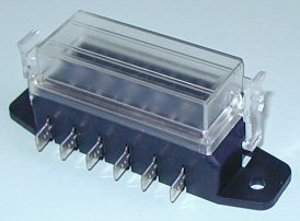
I simply ran a wire from the 5A accessory terminal to the relay, and connected a heavy gauge cable (using an old battery jumper lead) from the battery positive terminal to the relay. The relay then feeds the surface-mount 8-way covered fuse box. At the fuse box, I put a female spade terminal on each of the male fusebox terminals, stripped a long length of the jumper lead, and soldered it in place at each female spade terminal. (To form a sort of common bus bar).
Then using some "Polymorph" (low temperature mouldable plastic) the entire lot was insulated.
The auxiliary fuse box itself I located on a piece of plywood in the tail housing (I later installed a second one into the Givi top box because I ran out of fuses!)
The connectors are used as follows:
| Primary fuse box | Secondary fuse box | ||
|---|---|---|---|
| Connector # | Connected to: | Connector # | Connected to: |
| 1 | Autocom | 1 | Radio |
| 2 | GPS | 2 | Remote control sender |
| 3 | Auxiliary driving lights | 3 | Air pump (defunct) |
| 4 | Radio remote control light | 4 | Spare |
| 5 | Heated gloves | 5 | Spare |
| 6 | Heated grips | 6 | Spare |
| 7 | Stebel Nautilus horn | 7 | Spare |
| 8 | Secondary fuse box | 8 | Spare |
Apart from providing a mounting point for the first fuse box, the plywood also provides a solid base for the Autocom unit. Here's a photo (obviously taken before the top box was mounted):
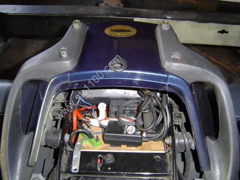
A heavy gauge cable also runs from the battery negative terminal to a common connector (coloured green in the photo).
The white plastic "pillar" you can see just to the left of the Autocom is a removable plastic cover, which insulates a copper post which is connected to the live feed from the battery. The problem with a Pan European is that if you ever have a flat battery, in order to connect jumper leads, you first need to remove the seat, then the left pannier, then the entire left side panel in order to access the battery. The copper post shown here enables the easy connection of jumper leads, and only the seat needs to be removed.